VDATP
Getting to know VDATP
A VDATP system typically consists of two units - the top unit and the bottom unit - as well as an aluminum rail structure. Each unit has the following features:
- 100 ultrasonic transducers, in a 10x10 array
- a Cyclone 10LP (part number 10CL016YU256I7G) FPGA, with JTAG connector available. This generates the signals to drive the transducers, as well as controls various other parts of the unit
- FPGA configuration memory (typically not populated)
- 350mA RGB LED drivers with LEDs (generally only available on upper units)
- 32MB DDR RAM
- a connector for up to 2 external ultrasonic microphones
- up to 36V power regulation, with reverse polarity protection
- programmatically adjustable transducer power supply (4.5V-18V)
- embedded Raspberry Pi Zero 2 W to program and control the FPGAs (generally only available on bottom board)
- 3D printed enclosures
The two units are connected with a 12 wire cable that is 12" long. This allows the distance between the top and bottom boards to be adjusted as required. This cable passes commands from the Pi, a synchronization signal between the two boards as well as signals necessary for the PI to program the FPGAs.
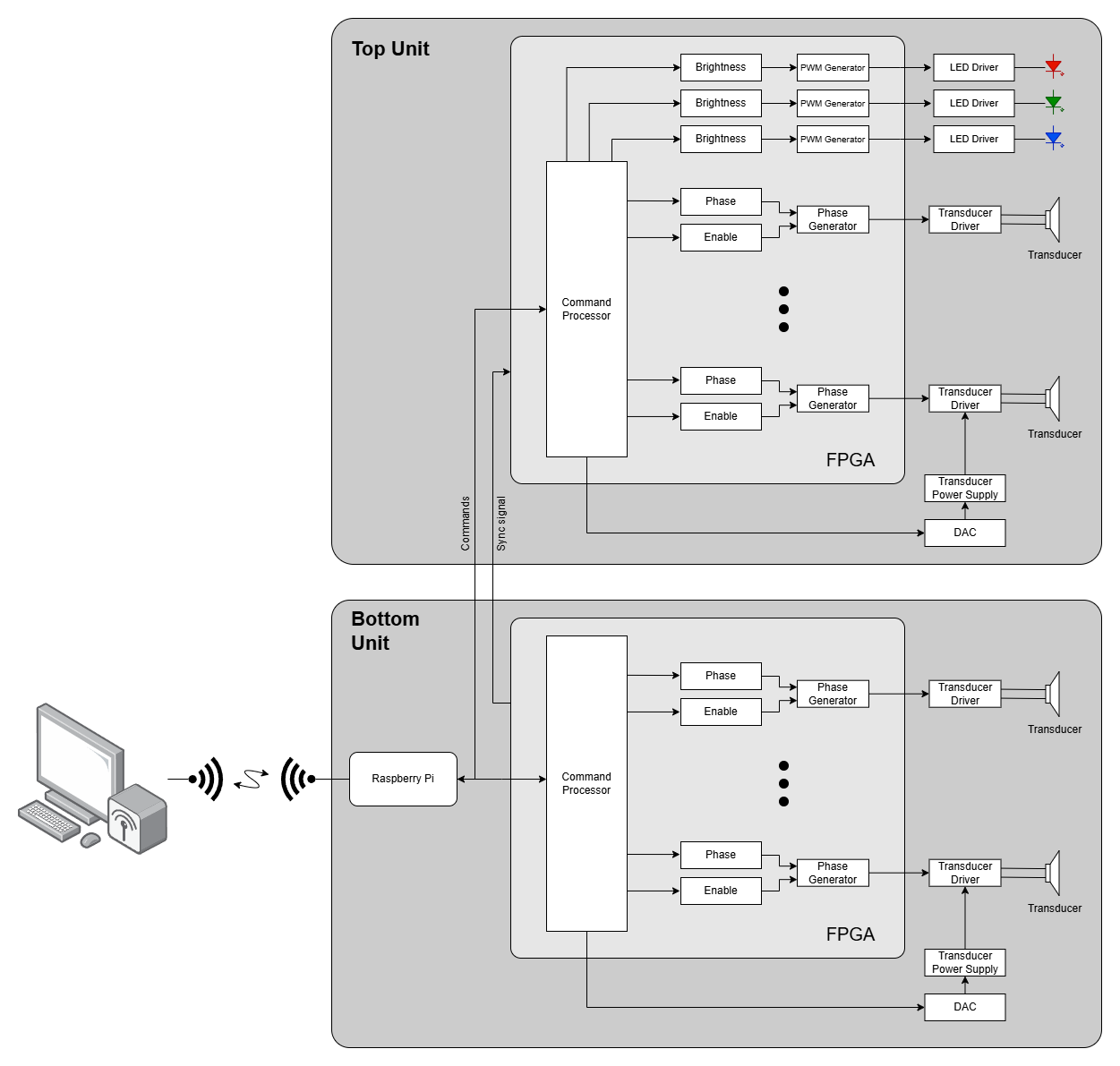
VDATP block diagram